Hardware Design
The hardware design is based on the Adafruit HUZZAH32 ES32 feather open source board
The general architecture of the system is shown below.
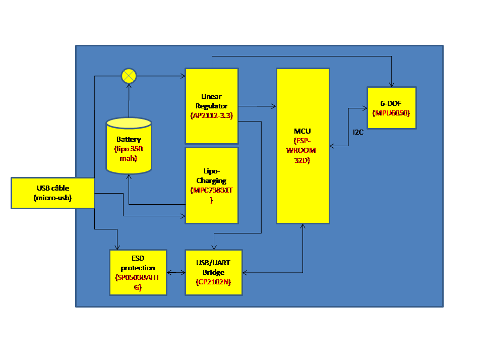
- The design is broken down into seven major sections :
Power supply and filtering,
Lipo charging,
USB to serial converter + ESD protection,
MPU6050,
ESP-WROOM-32D & Autoreset,
Reset circuit,
Boot circuit,
Adressable LED.
Power supply and filtering
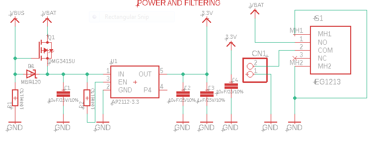
The board can be powered from a 5V USB port (VBUS), or from a 3,7 V LIPO (or Li-Ion) 1S battery.
The battery is connected to a switch that allows the battery supply to be turned ON/OFF.
A DMG3415U (MOSFET transistor) is used to switch between VBUS and VBAT. When VBUS is not present, the gate is pulled low, and the MOSFET shorts out the body diode, connecting VBAT directly to the LDO. When VBUS is greater than VBAT (that is our case if the board is connected by usb), the MOSFET is cut off and the body diode is blocking, disconnecting VBAT from the circuit. EN pin of the DMG3415U is pulled low to permanently enable the chip.
So with this switch, VBAT enters to the AP2112-3.3v LDO, if VBUS isn’t present, otherwise VBUS enters to the AP2112-3.3.
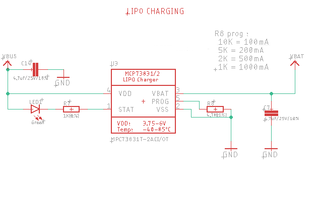
Lipo charging
The lipo charging circuit is based on the MCP73831/2 microchip chip. This chip is a miniature single cell, fully integrated Li-Ion, Li-Poly charge management controllers. Typical Application schematic is used.
Note
R8 resistor is used to set the current regulation. As we will used battery around 350 mA, we fix R8 to a current regulation around 200 mA.
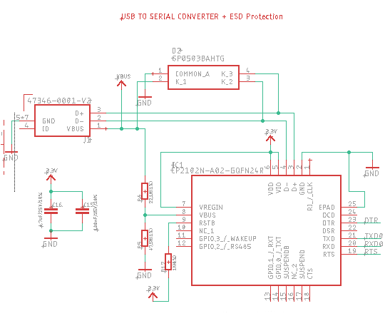
USB to serial converter + ESD protection
The USB serial converter is based on a CP2102N from Silicon Labs.
ESD protection is done using a SP0503BAHTG from littlefuse as recommended on the datasheet.
VEREGIN, VDD & VIO pins are tied to +3.3V, and also RSTB pin as recommended on the datasheet.
Two decoupling capacitors are also used.
To detect when the device is connected to a bus, which is defined as VIO – 0.6 V, a resistor divider on VBUS is required to meet these specifications and ensure reliable device operation. In this case, the current limitation of the resistor divider prevents high VBUS pin leakage current, even though the VIO + 2.5 V specification is not strictly met while the device is not powered.
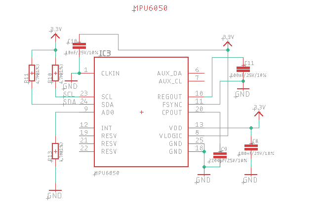
MPU6050
The circuit for the MPU6050 is a typical application scheme (see datasheet). SDA and SCL pins are connected to the pins 22 & 23 of the ESP-WROOM-32D with two pullup resistors.
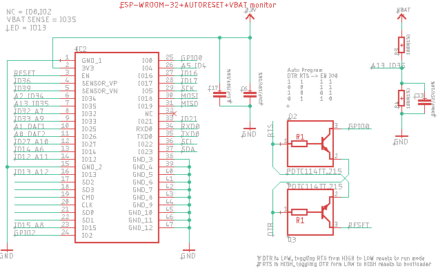
ESP-WROOM-32D & Autoreset
ESP-WROOM-32D chip, is the last ESP-WROOM-32 update from espressif. As our board is design with built-in USB to Serial converter, we will use esptool.py to automatically reset the board into bootloader mode. esptool.py can automatically enter the bootloader by using the RTS and DTR modem status line to toggle GPIO0 and EN automatically.
EN pin forces the ESP32 chip to reset and the ESP will enter the serial bootloader when GPIO0 is held low on reset. Otherwise it will run the program in flash.
Note
GPIO0 has an internal pullup resistor, so if it is left unconnected then it will pull high.
We use two PDTC114T (an NPN transistor with resistor) to control the ESP32 Boot mode Selection.
We have DTR controlling the base of a transistor whose collector is connected to RESET. We have RTS connected to the base of a transistor whose collector is connected to GPIO0. Remember, there is an external pullup resistor on RESET so default is HIGH.
When DTR is set HIGH and RTS is set LOW, this pulls RESET to LOW and GPIO0 is not controlled so it will eventually take its strapped value of HIGH. This has the same result as assuming DTR connects to GPIO0 and RTS to RESET. The processor is in the reset state.
When DTR is set LOW and RTS set HIGH, this disconnects RESET from the transistor and it gets pulled HIGH by the external pullup resistor. At the same time, GPIO0 is pulled to LOW by the transistor (with its internal pullup still engaged). This has the same result as assuming DTR connects to GPIO0 and RTS to RESET. The processor comes out of reset state and reads the GPIO0 value to be LOW to start the bootloader.
Battery voltage is measure using a a voltage divider bridge connected to the IO35 pin.
Most of the other pin are not used, unlike IO22 & IO23, set respectively on SCL and SDA I2C signal to communicate with the MPU6050.
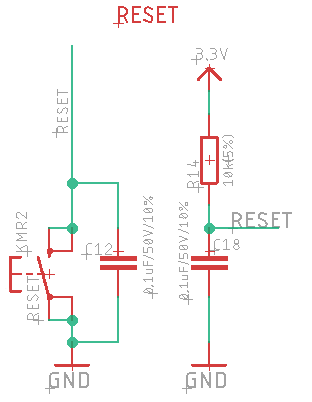
Reset circuit
Enable (EN) is the 3.3V regulator’s enable pin. It’s pulled up, so connect to ground to disable the 3.3V regulator. So we connect this pin a pushbutton to restart your ESP32.
As recommended by espressif a RC circuit with a resistor of 10k and a capacitor of 0,1uF is added between EN pin and +3,3V to make automatic reset more reliable.
Boot circuit
Boot switch is connected to GPIO.
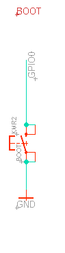
Note
Some ESP32 based schematics mention a 0,1uF capacitor in parallel to the BOOT button to debounce. Do not add this capacitor in this design or you will not be able to start the board without pressing the EN button.
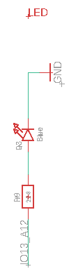
Adressable LED
The adressable led is connected to the pin IO13 of the ESP-WROOM-32D. This led is used to display the status of the MPU6050 calibration.
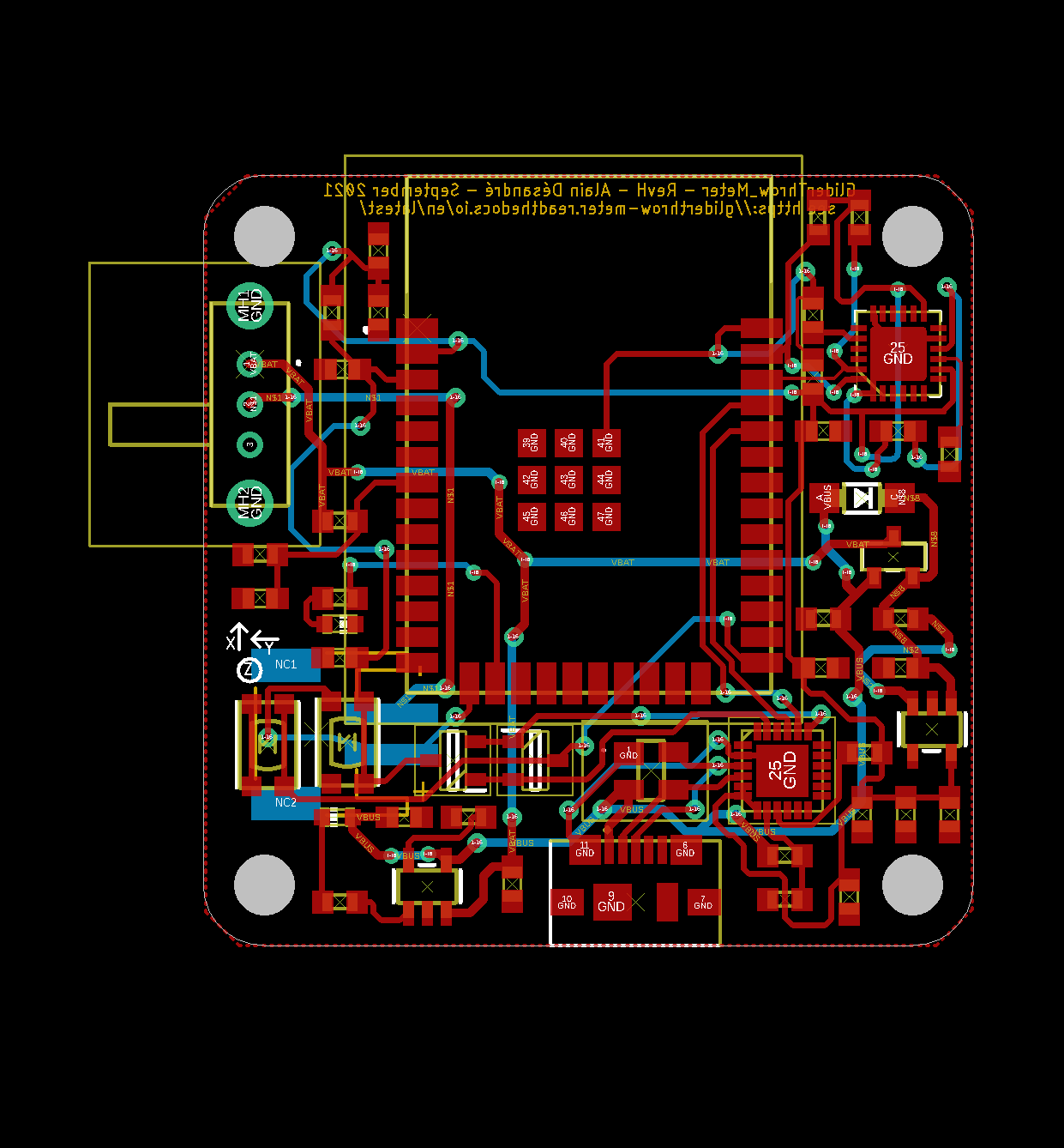
PCB routing
The routed PCB (without ground plan) is shown below. The routing was done under EAGLE.
3D made with fusion 360 is shown below.
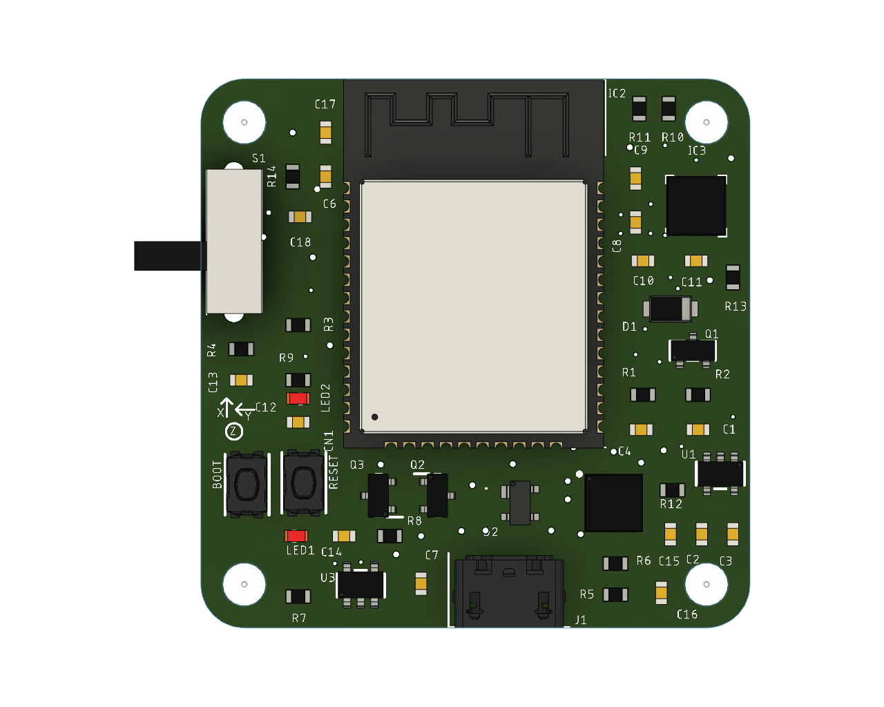
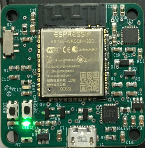
The finish board is shown below (quiet similar to the 3D model isn’t it :-)
Bill Of Material, Eagle Files & Gerber
BOM can be downloaded at this link bom.xlsx
Pick & Places file can be downloaded at this link Pick&Place file The format of this file is compatible with the Smt Assistant utility from Alciom. SmtAssistant is a software designed by ALCIOM and helping to locate a part on a printed circuit board, based on a bitmap of the PCB and Pick&Place file. SmtAssistant is a useful for manual prototype assembly, inspection or board repair works. see here for more information and download.
Gerber files can be downloaded at this link ESP_MAD_Gerber.zip
Eagle files can be downloaded at this link eagle-files.zip
Let’s move on to the next chapter for the description of the system assembly and its use.